2-Particle Tracking
The Particle Tracking Module (Figure 2-1) estimates the path along which a synthetic particle travels from an OSTDS, which is the point where the effluent enters the surficial aquifer, to a receiving water body. The flow field is based on the Groundwater Flow Module outputs, which are the direction velocity and direction magnitude raster images to determine the flow path of the imaginary particle. The flow path is used to calculate the contaminant plume’s advective transport from any OSTDS. The output of the Particle Tracking Module is a polyline shapefile containing a set of flow paths from the septic tank locations along the gradient of the water table. The Transport Module uses these particle paths to incorporate flow heterogeneity in the plume calculation.
Sinks or pits in the DEM are problematic for generating flow paths since they cause the flow to become trapped. The toolbox allows filling any sinks to their nearest pour point. The pour point is analogous to the location along the rim where liquid overflows a water-filled bucket. More details of using the sink filling option are given below.
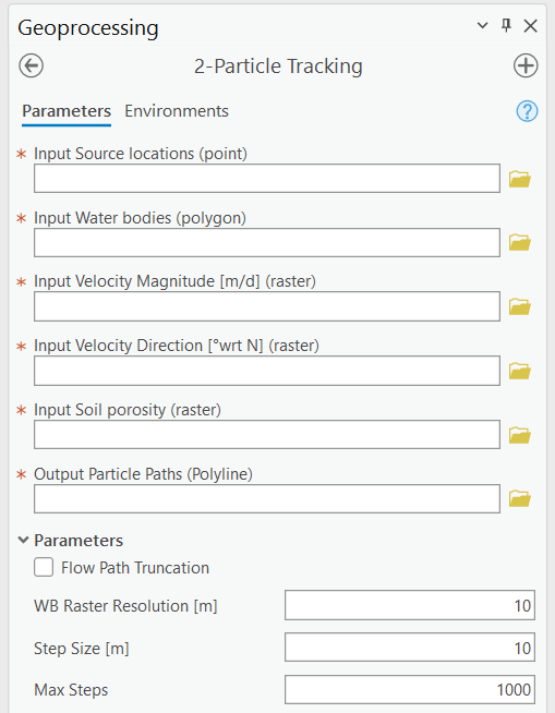
Figure 2-1: The Particle Tracking Module.
Input Layers
Input Source locations (point): A point feature layer specifying the OSTDS locations. If the exact locations are unknown, they can be approximated by geometric centers of property parcels.
Input Water bodies (polygon): The locations of water bodies used by the Groundwater Flow Module. If a flow path intersects a water body, the path is terminated at the water body.
Input Velocity Magnitude [m/d] (raster): This is the magnitude raster generated by the Groundwater Flow Module. The magnitude information calculates an average velocity (harmonic mean) value along the flow path for the Transport Module.
Input Velocity Direction [°wrt N] (raster): This is the angle direction from the north of each grid cell. The direction raster is the output of the Groundwater Flow Module.
Input Soil porosity (raster): The soil porosity used by the Groundwater Flow Module. The information calculates an average porosity (arithmetic mean) value along the flow path for use by the Transport Module.
Options and Parameters
Flow Path Truncation: The truncation option trims line features (flow paths) intersecting the water body polygons and extends particle paths that fall short of the water body polygons. This option is merely for better visualizing the flow paths and does not affect any calculation of flow paths and nitrogen transport. Enabling flow path truncation requires more computer time for the post-processing of flow paths.
W.B. Raster Resolution [L]: This is the water body raster resolution. The resolution is in map units, which convert the water bodies’ polygon to raster. The default value is automatically set to one-half of the velocity-direction raster cell size, determined by the DEM resolution. This value should only be changed if the default does not provide satisfactory results, as explained in the troubleshooting notes and Figure 2‑2.
Step Size [L]: The length of each flow path segment (in map units). The default is automatically calculated to equal the value of W.B. Raster Resolution. This value should only be changed if the default does not produce satisfactory results (see troubleshooting notes below).
Max Steps: The maximum number of steps before terminating the path. This parameter prevents infinite loops by ensuring there is always a stopping criterion for particle tracking. The default should suffice for most circumstances.
Outputs
Output Particle Paths (Polyline): A polyline shapefile containing line segments representing the path of a particle starting from each source point and moving through the flow field. Any given path from a source point (i.e., OSTDS) to a water body is composed of a series of line segments (of length Step Size) in which the hydraulic conductivity and soil porosity are assumed constant within each segment. Each entry in the shapefile’s attribute table corresponds to a single segment.
Table 2-1 shows the fields in the shapefile’s attribute table. The Transport Module calculates the average velocity and porosity values using this table. Details of the attribute table are only needed for advanced uses of the software (e.g., visualization discussed in Section 5.11); general users do not need to understand the meaning of each item of the table.
Field Name |
Description |
|---|---|
PathID |
The FID (unique identifier) of the corresponding point (i.e., septic tank location) in the Source Locations point feature class. All path segments corresponding to the same source have the same PathID value. |
SegID |
The ID of the current segment. This ID is assigned in sequence with 0 corresponding to the first segment in the flow path for any given PathID. |
TotDist |
The total cumulative travel distance for the current segment. |
TotTime |
The total cumulative travel time for the current segment. |
SegPrsity |
The porosity at the starting point of the current segment. |
SegVel |
The velocity at the starting point of the current segment. |
DirAngle |
The angle of the current segment. |
WbID |
The water body’s FID intersects the current segment’s starting or ending point. If no water body intersects the current segment, this value is -1. In a sequence of segments corresponding to a given PathID, only the final segment should have a value other than -1. If the sequence does not terminate at a water body, all segments have a value of -1. |
PathWbID |
The FID of the destination water body. The value of this field is the same for each segment and is equal to the value of the WbID of the final segment in the path. |
Troubleshooting
Table 2‑2 lists a possible issue encountered during model execution, a probable cause, and a possible solution. Note that the error messages may appear for reasons other than those listed. If you cannot find a solution to the issue, then please submit a [New issue] in the ArcNLET-Py GitHub repository (Issues · ArcNLET-Py/ArcNLET-Py · GitHub) as described in the GitHub instructions at Creating an issue - GitHub Docs.
Error |
Cause |
Solution |
|---|---|---|
Particle paths appear as vertical or nearly vertical lines. |
The selection of input magnitude and direction layers have been reversed. |
Make sure the correct magnitude and direction raster are selected. |
Particle paths may travel through a water body, depending on the value of the W.B. Raster Resolution parameter and the Step Size parameter. This phenomenon is related to the Step Size, as explained in Figure 2‑2a, which shows a small creek that is 6 m wide. The thin blue lines represent flow paths. Note that the leftmost line crosses the creek while the other four exhibit the expected behavior and do not cross it. This behavior is because the leftmost particle path does not “see” the creek, as demonstrated in Figure 2‑2b when the creek is converted from a polygon to a raster with a 1 m cell size. The particle tracking algorithm detects whether the path has reached the water body by checking whether the starting or ending point of the flow path segment overlaps a raster cell that represents a water body. The red feature in Figure 2‑2b shows the segment “skips” over the creek because the segment length is too large and is positioned so that neither the starting nor ending points coincide with the creek’s location. This situation may be remedied by selecting a smaller value for the Step Size parameter.
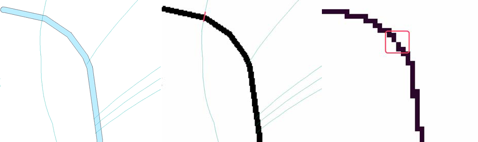
Another possible reason for a flow line to cross the creek is that the W.B. Raster Resolution is too large to represent the creek accurately. This scenario is shown in Figure 2‑2c in the area indicated by the red box. In Figure 2‑2c, the creek is illustrated with a raster resolution of 5 m. In this case, because of the coarse resolution, there may be a gap in the water body’s raster representation, enabling the flow path to “leak” through the gap indicated by the region within the red box. This situation may be remedied by selecting a smaller value of the W.B. Raster Resolution parameter or by increasing the width of the narrow creek (if it is reasonable).
Another potential problem of the particle tracking function is that the flow path may be trapped in a sink or pit close to the water body. A sink can exist very close to the water body, even if sinks have been filled. The sinks are due to converting the water body from a polygon to a raster format in conjunction with the superposition of the smoothed, unfilled DEM in areas overlain by the water body (see Section 2.2.2, Fill Sinks parameter). The DEM raster cell containing the sink may lie slightly outside of the polygon representation of the water body but is contained within the raster representation of the water body. In this case, flow may become trapped in the sink before reaching the water body. This scenario may be treated by manually modifying the boundary of the water body to extend over the sink.